Electronic Engineering Manufacturing Services
As specialists in design to order services, we offer products covering the entire spectrum of the industry
With years of experience and reputation in providing design manufacturing services to large enterprises, Portwell Europe is your right partner for every aspect from initial concept to the complete system assembly and after sales service. Our mission is to make your ideas reality and set standards of tomorrow that will improve the quality of life for us all.
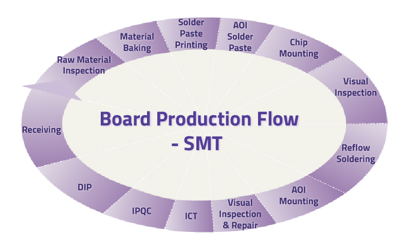

Step 1:
Raw Material Inspection
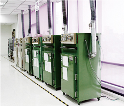
Step 2:
Material Baking

Step 3:
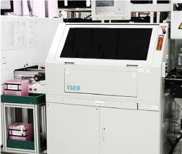
Solder Paste Printing

Step 4:
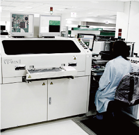
AOI - Soldering Paste
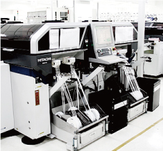
Step 5:
Chips Mounting
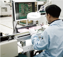
Step 6:
Visual Inspection
Step 7:
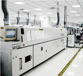
Reflow Soldering
Step 9:
Visual Inspection
Step 10:
In-Circuit Testing (ICT)

Step 11:
IPQC
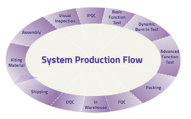

Step 1:
Assembly
Step 2:
Visual Inspection
Step 3:
IPQC

Step 4:
Basic Function Test

Step 5:
Dynamic Burn In Test

Step 6:
Advanced Function Test

Step 7:
Packing
Step 8:
FQC

Step 9:
OQC

Step 10:
Shipping
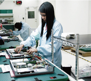
In order to ensure that the products will not be affected by ESD during production, an ESD control procedure is in place to meet standards.
For operator
- Wear anti-static suits and wrist straps in the factory.
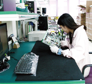
For operator
- Cover the anti-static tape on cables and test tools which are used in board functional testing.
- Use acrylic shelves which may prevent electrostatic charge buildup.
- Cover keyboards with an anti-static membrane to protect units under test from electrostatic damage.
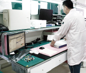
For equipment
- Each device and working area is grounded and tested periodically to confirm that the ESD measurement is normal.
For component
- Suppliers of ESD sensitive components are required to handle and ship them in a protective manner.
- Anti-static packaging is designed to prevent failures due to electrostatic charge build-up.